Legs
I prepared the legs for the Upprätt 2 armchair by making a final milling pass through the jointer and planer. Due to limitations of the elm plank I'm working with, I had to cut the curves in the back legs fairly close to the final shape. This limits the number of reference surfaces I can rely on for accurately locating joinery, but as you will see... there's always a way.
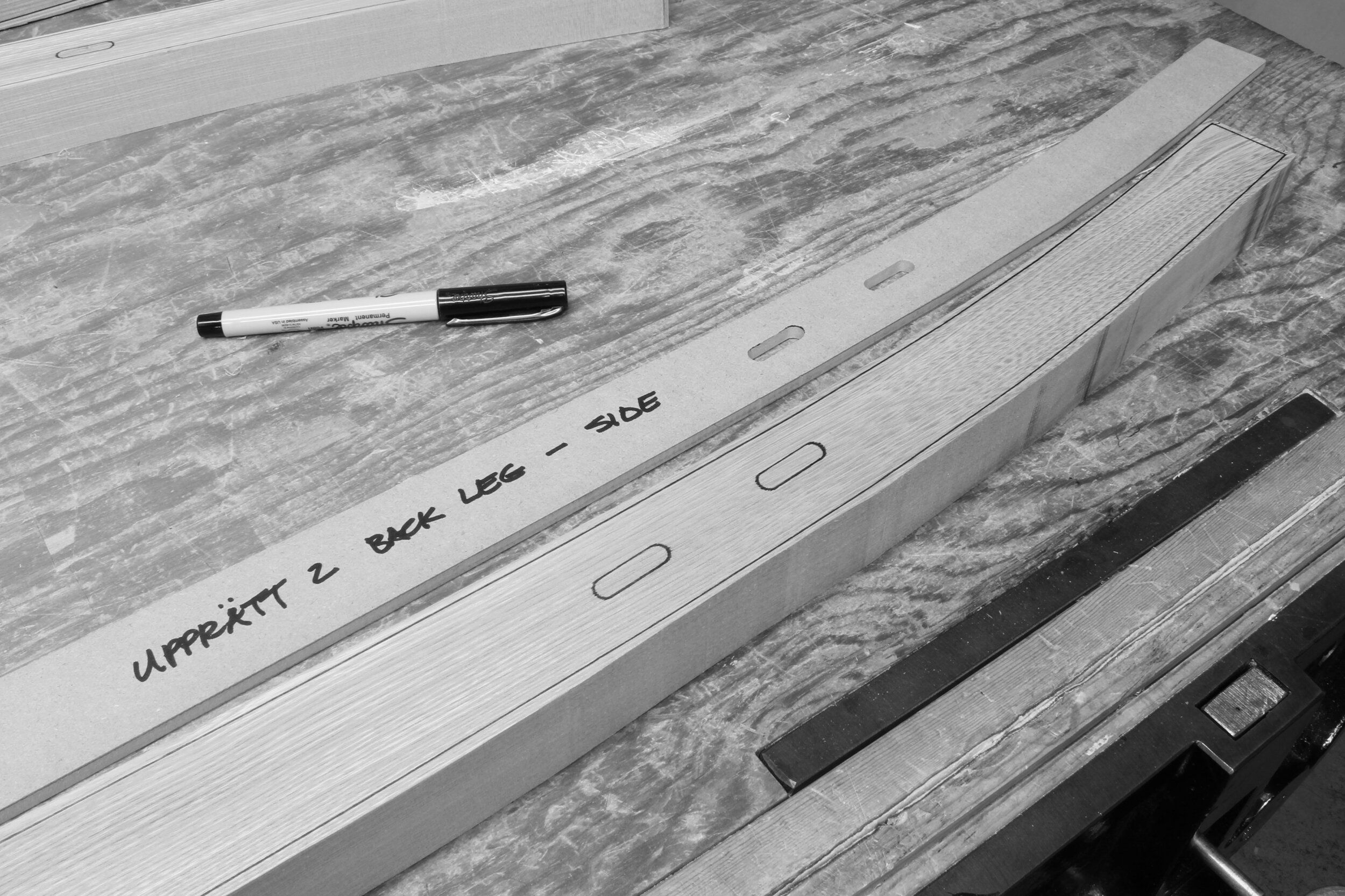
With the back legs machine-planed down to their final nominal thickness, I positioned the template and traced the leg outline, including the joinery. Next, it was back to the bandsaw to cut to the traced lines.
Below, I've clamped both back legs into the vice and proceeded to hand-plane the curved surfaces to the template lines.

Progress is fairly quick, so frequent checking of the template lines is always a good idea.

The concave curve of the back legs is done with a compass plane and spokeshave.
Satisfying results.

One advantage of using a computer model, even when the project is mostly handwork, is that I can create templates that represent the actual curved surface. Below, I'm transferring the template to the front surface of the back legs.

Already, you can see some of the curved grain graphics that are resulting from the added effort last week to orient the end grain angle toward this intended result.

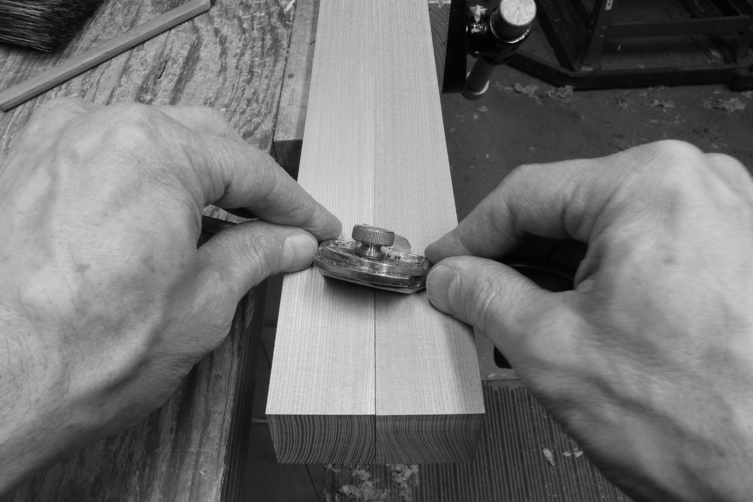
Mortises are being cut on my Davis & Wells boring machine that I converted to cut slot mortises. Below is one of the front legs. This is a straightforward operation, since the leg stock is nicely square and straight, and in alignment with the mortises.

Things get a little more interesting with the back legs. The leg sides make nice reference surfaces, but additional work is needed to deal with the curved front and back faces.

The jig shown here holds the leg sides at 90° to the mortiser table and allows me to set the top end face of the leg at exactly 90°, as well. From there, the mortising proceeds as usual; pictured below is the mortise for the back that is attached to the top of the leg.

When it came time for the back seat rail and back stretcher mortises, I clamped both legs to a squared-up block of wood... in effect adding a new reference surface for setting up the mortising.

After completing all the leg mortises, I traced the last of the leg template shapes onto the legs and shaped the surfaces; first with the bandsaw and then with hand planes and spokeshaves.

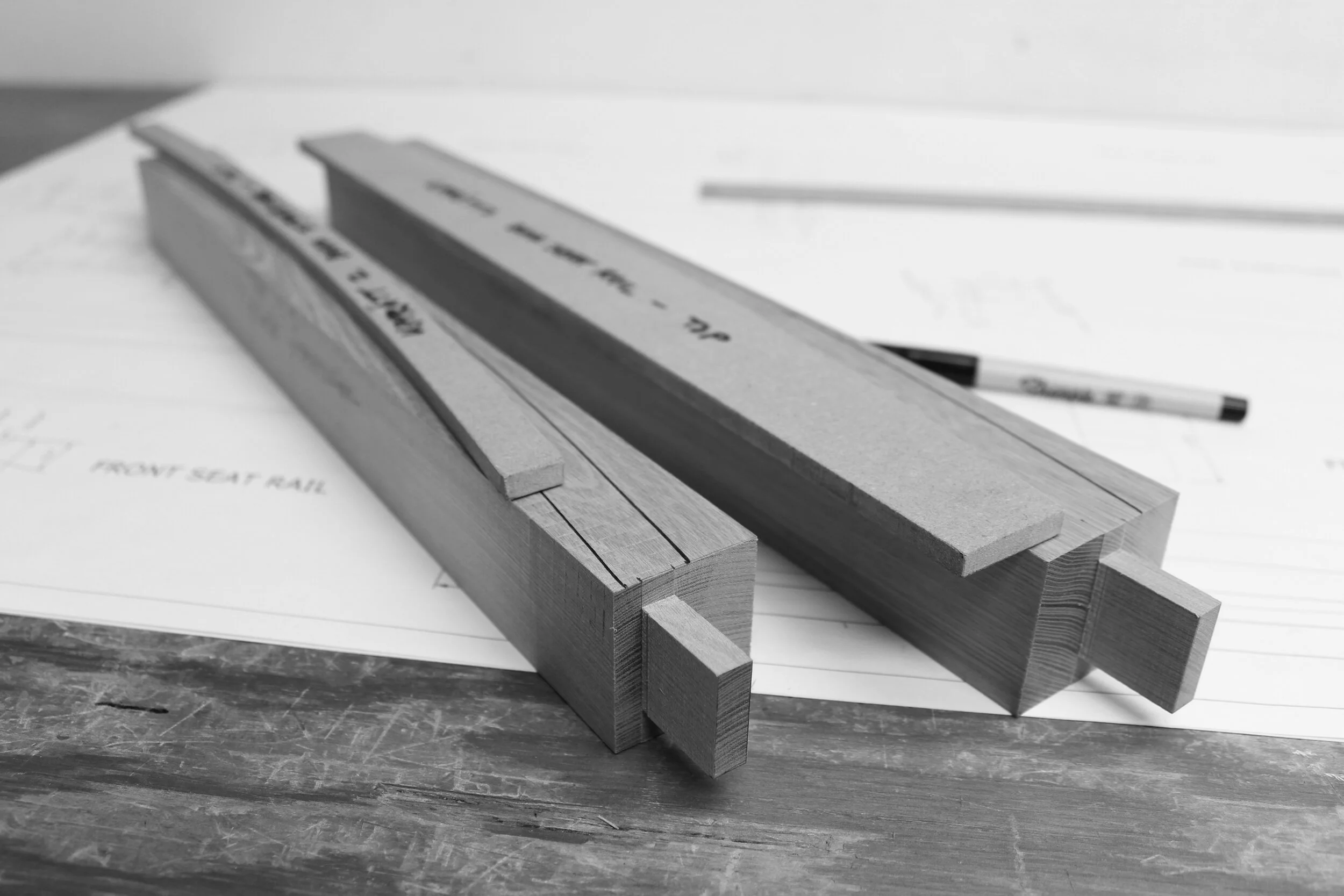
I've got my sights set on the first glue-up of the back assembly for next week. I've begun work on the back seat rail and back stretcher. After final machine milling of the parts, I laid out the tenons on the ends.

Cut the shoulders on the table saw.

Cut the tenon cheeks on the bandsaw and traced the templates.
I'm looking forward to fitting these tenons next week and preparing the surfaces and edges for the first glue-up. Until then...
Hej då!
Craig